Toolbox
There is probably no better workout in trucking than manually hoisting a loaded trailer that is resting a foot below the frame of the tractor assigned to pull it. But it’s hard to appreciate the task’s physical benefits when you’re panting like a dog and cussing the idiot who caused the problem.
Nearly all truckers eventually encounter trailers requiring a few heartfelt turns of the landing gear crank. If they are lucky, the mechanism will be in good repair and well-greased.
Unfortunately, that isn’t the norm, says Lee Brace, president of Jost International. “Lack of maintenance is the biggest source of trouble affecting landing gear,” he says. People simply forget to keep the system lubed.
“We always tell people to grease their landing gear every three or four months,” he says. The job is fairly quick, involving just a few zerks, but it does require that the legs be fully extended beforehand to ensure the elevating screw gets adequate lubrication. Brace says operators should use high-grade lithium grease, which won’t turn into putty when ambient temperatures sink below zero.
Misuse and abuse are two other contributors to landing gear failure. Brace says the systems should be periodically operated to keep them working smoothly. Also, both legs should be firmly planted on a solid supporting surface before a trailer is unhooked from a tractor. Some people stop cranking while there’s still a gap between the legs and ground, causing the trailer to drop hard when they pull away. Brace says that sort of carelessness eventually strips the threads of the elevating screws, rendering the legs useless.
The best way to preserve landing gear is to dump the air from your tractor suspension to gently lower a trailer onto its legs. It’s also a good idea to dump the air before picking up a trailer, using the suspension to lift the weight off the legs.
Landing gear comes in two main varieties: internal gearbox and external gearbox. Jost makes the former, and Holland/Binkley makes the latter. The parts needed to rebuild either type generally cost $40 to $100, depending on the extent of the trouble. A complete set of legs sells for $275 to $325. Such a narrow price spread encourages many truck owners to replace, rather than rebuild, their malfunctioning landing gear. However, today’s razor-thin operating margins have a lot of people looking for savings wherever they can find them.
Rebuilding usually involves the gearbox side of the set, which has more moving parts. Most of these chores require that the leg be removed from the trailer. Some welding is often necessary. Barring any unforeseen complications, wrenching normally takes less than two hours.
The fix
Landing gear legs are heavy, and the weight they support is even heavier, so safety is critical. Always properly block and support a trailer before removing its landing gear. If possible, hook it to a tractor and set the brakes. These steps apply to the repair of a Jost internal gearbox. This procedure is easier with the leg in an upright position.
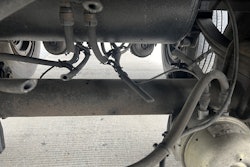
1. Isolate the problem. Because both legs of a landing gear operate together, it’s necessary to determine which of them is causing the problem. Disconnect the cross tube between the legs and operate each individually. Use a long bolt or punch, poked through the bolthole of each cross-tube shaft, to turn the gears.
2. Remove landing gear. Crank the affected landing gear leg down until it lightly touches the ground. Unbolt the leg. Use an acetylene torch or carbon disk to cut welded braces free. The amount of welding varies by trailer brand.
3. Remove crank and leg cover. Manufacturers typically spot-weld the nuts and bolts used to attach landing gear cranks. Cut the bolt off with a Sawzall. Remove the two small bolts holding the leg’s cover.
4. Remove upper shaft assembly. If the leg has been properly maintained, its top cavity will be filled with grease. This must be removed to get at the gears. Grease that is free of contamination and metal bits can be stored in a clean canister and reused. The upper shaft assembly is composed of one large gear, one small gear, a short shaft and two roll pins. Use a center punch to mark the end of the shaft farthest from the large gear to ensure proper reinstallation. Drive out the roll pins with a punch and hammer. Remove the parts and group them.
5. Remove lower shaft assembly. Pry out the plastic plug in leg housing. Move the crankshaft, or input shaft, to its high-speed position. Rotate the gears until the shaft’s roll pin is aligned with the plug’s side-access hole. Use a punch to drive out the pin. A special curved punch is required for legs that lack the access hole. Remove the cross-tube, or output, shaft from the large gear. Loosen and remove the four nuts holding the shift housing. Carefully remove the crankshaft and shift housing together. Pulling the crankshaft out of the housing will release a small internal spring and two metal balls, which are easily lost. Wrap a shop towel around the crankshaft inside the shift housing and slowly separate the parts. The towel will keep the spring and balls from launching across the room. At this point, all that remains in the cavity are two gears – one that rotates vertically, the other horizontally. Both must be lifted out together. Group the parts.
6. Clean and inspect parts. Remove the pin and washer at the base of the cavity; then, with a helper, lift the outer housing off the inner leg assembly. Degrease all the parts with a solvent cleaner. Closely inspect the elevating screw and look for worn, cracked or broken threads. Such defects qualify a landing gear leg for junk status because elevating screws cannot be replaced economically. Check the gearbox assemblies for missing gear teeth. Also, examine the shaft bushings – there are five – in the housings. Replace any that show wear. They’re easily tapped out and in with a small hammer.
7. Grease and cover elevating screw. Repack the elevating screw’s thrust bearing with grease. Coat the screw’s entire surface with grease. Slide the outer housing over the internal leg assembly. Install washer and pin.
8. Assemble lower shaft. Place the small spring and balls inside their hole in the crankshaft. If necessary, constrict expansion by tightly wrapping cellophane tape around the shaft. The tape will eventually dissolve. Slide the assembly through the shift housing. Fit the two large lower gears together and slide them into place over the top of the elevating screw. The horizontal gear rides inside the vertical gear. Insert the cross-tube shaft into the vertical gear. Then, from the other side, insert the crankshaft assembly and secure it with four lock nuts. Rotate the gears until the roll-pin holes align vertically. Tap in the pin with a hammer and punch.
9. Assemble upper shaft. The large upper gear is positioned on the cross-tube side of the housing cavity. Insert its short end in the housing bushing; then put the smaller gear into place and align it with the larger. Poke the short shaft through the crankshaft-side bushing and into both gears. Make sure your center-punch mark is on the outside end. Line up the roll-pin holes and tap in the pins. Operate the assembly in low and high gears to ensure that everything turns freely.
10. Fill and enclose. Cover the side-access hole with silicone or a new plastic plug. Fill the housing cavity with high-quality, temperature-stable grease. Inject a little more grease through the zerks to make sure they’re functioning properly. Before securing the cover, check it for cracks, holes, deformation -anything that would provide an opening for moisture. Replace it if necessary. Attach the crank, using a high-grade bolt and locking nut.
11. Reattach leg. Secure the leg to the trailer using new grade 8 bolts. Weld up the necessary bracing. Before connecting the cross tube, ensure that both legs are completely retracted so they’ll be vertically aligned.
Is there something you would like to know how to do? Overdrive wants to hear from you. Send letters to Overdrive editorial, P.O. Box 3187, Tuscaloosa, AL 35403, or e-mail Laura Crackel at [email protected].