Technician Ernie Fry at Associated Truck Parts in Gilbertsville, Pa., uses a special tool to press out the u-joint cross, so the parts will fit tight when reinstalled.
Experienced Class 8 tow truck drivers arriving on the side of the intestate to pull in a broken down big rig will tell you one cause never surprises them. A broken U-joint.
“You do actually have to grease the joint,” says David Goode, owner of Goode Towing and Recovery based in Killeen, Texas, “and if you do it will last. If you don’t it won’t.”
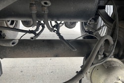
The driveshaft typically consists of two U-joint assemblies linked by a thin steel tube. The joint at one end has a sliding, splined section called a slip-yoke, so the shaft’s length can change when the truck goes over bumps. If the shaft is long enough, there is also a center bearing that helps support it. This is typical of the shaft connecting the rear of the transmission to the forward drive axle.
The tube between the U-joints actually proves to be the weak point in the drivetrain under many circumstances, bending severely and saving the U-joints, transmission and axle parts in the process, when severe overstrain occurs. A typical example of conditions that produce overstrain is a very heavy vehicle crawling out of a muddy spot and developing a hop.
Popping the clutch or releasing the clutch rapidly with too much engine rpm are also common causes of driveshaft failure. Still another is spinning on ice and having the tires catch on a dry spot.
If properly assembled, balanced and installed, driveshafts still need regular greasing and, because of the way too much torque or even normal wear can put them out of balance, regular inspections. Even under favorable operating conditions, U-joints still need to be disassembled and the needle bearings and caps replaced when they wear out.
We visited Associated Truck Parts in Gilbertsville, Pa., to find out about doing driveshaft repairs the right way. This heavy-duty specialist is a dealer for ArvinMeritor and several other major vendors of driveshaft parts. Technician Ernie Fry uses an array of expensive special tools and sophisticated equipment, along with many years’ experience, to artfully turn out driveshaft assemblies that are properly balanced and phased. (Phasing refers to having the two U-joints at the proper angle to one another, which is the only way to minimize vibration.)

Fry spends most of his time either rebuilding worn or damaged U-joints, or replacing bent driveshaft tubes. Tubes may also be replaced to change a driveshaft’s length when customers are modifying vehicle suspension systems to improve weight distribution, or for other reasons.
Rebuilding U-joints
This is a lengthy process. We can only hit the high points here, showing the kinds of special tools and care a good shop gives this work.
- It’s necessary to pull parts apart without damaging them. Fry always removes the zerk (grease) fittings first. Otherwise, they can be damaged during disassembly.
- The bearing caps should fit tight in the yoke, and the cap’s two parts, which are spot-welded together, must not rotate in relation to one another. If caps are loose in the yoke, so turning the cross rotates the cap, the yoke has probably been mechanically overstressed. If a new cap has play, the yoke should be replaced. Fry then uses a special tool to force the bearing caps out of the yoke.
- Next, he uses a special tool to press out the cross. This kind of tooling makes his job easier and also preserves surfaces so parts will fit tight when reinstalled.
- Once the yoke is disassembled, Fry uses a wire brush to clean out rust. Edges roughened during removal have to be filed smooth so the cap won’t be damaged when it is replaced.
- Burrs have to be removed from the cap seating surface so the cap will seat flat when it is replaced.
- The new needles, assembled inside the caps, must be thoroughly packed with grease.
- As the cross is assembled into the yoke, Fry makes sure the two grease fittings will line up (so when you go to grease later, the job is easier). This is a tricky business because you have to slide the parts together skillfully and in the right order so the needle bearings won’t fall out during assembly.
- This particular design uses Loctite, factory applied to a knurled bolt that is renewed every time to keep the torque in spite of vibration. Many other designs use locking straps that must be bent against the bolthead’s flats after assembly to hold them tight.
- The cap bolts are brought down evenly (in several stages) and then torqued to 40-40 pounds-feet. The torque wrench clicks when torque is correct.
- Of course, the other end of the U-joint assembly must be similarly assembled to the opposite trunnions on the cross.
- The U-joints for this shaft were later welded onto the new tube, and then the assembly was balanced, as described above. Even when there is no damage to the tube, and new crosses, needle bearings and caps are being installed to renew all bearing surfaces, the final step is a careful balancing.
Replacing a broken or bent driveshaft
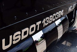
This driveshaft tube (below) failed after many years of hard service. There may have been a tiny defect in the weld at one end that allowed water in, eventually resulting in rust. The rust weakened the tube and, eventually, it gave up. This case serves as a reminder of the value of carefully inspecting driveshafts. Fry says the only sign of trouble would probably have been a tiny rust spot or fleck of missing paint at the welded seam where the tube was put together out of a flat metal sheet.
- The first step is removing the old tube from the joints at either end. Here, Fry uses a lathe to cut out off the tube end. Cutting the tough weld is hard work, and the blade has to be re-sharpened in the middle of the process.
- One of the larger challenges is measuring the length of a broken tube so the replacement can be cut to the same length. Fry measures the two sections at a reference point, adds the two dimensions together, then adds 1/8 inch. Fortunately, those sliding splines at one end will allow for a small error.
- The new tube must be checked for proper thickness with a ball michrometer, which can measure curved surfaces accurately. Fry elected to replace the broken tube, which was .139 inch thick, with an ArvinMeritor shaft material that was .180 inch thick, as a little reliability insurance.
- The tube is first cut to length in a large cutting machine. Fry then grinds a “chamfer” or angle into the end of the shaft both inside and outside. The inside chamfer makes it easier to press on the shaft, while the outside one leaves a nice groove for plenty of weld material.
- The parts are cleaned thoroughly in a solvent tank to help ensure the welds will bond thoroughly to the tube and yokes. Solvent must be cleaned out of the tube, or it will boil during welding and blow out the welds.
- The new shaft tube and yokes will be pressed together in a large device resembling a lathe, called a “weld press.” Special fittings are used to locate the yokes at either end during the work. Doing assembly correctly is complicated, and one of the toughest parts is aligning all the parts properly for correct “phasing.”
- Phasing means that the yokes are normally aligned in such a way that the joints at either end will be exactly 180 degrees (half a turn) out of phase, or in exactly opposite positions. This is done because U-joints don’t transmit movement to and from the shaft tube at a perfectly even rate, but slow down and speed up. Phasing them 180 degrees from one another equalizes the motion and helps ensure the shaft turns more smoothly. When the slip yoke at one end is disassembled, it must go back together with arrows aligned in order to keep the ends correctly phased.
- Fry takes an extra step and aligns the tube’s welded seam away from the crosses. He says the seam may be a tiny bit weaker than the solid metal, and this shifts the maximum stress away from that part of the shaft.
- He uses a level to check that the slip splines will be perfectly aligned with the yoke on the opposite end before forcing the parts together.
- Fry depresses a pedal to actuate the press via air pressure and start squeezing the ends together. As the parts are going together, a gentle tap with a light hammer will often help make sure the yokes enter the shaft straight. The end of the tube must just touch the shoulder cast into the yoke. Pressing too far can damage the end of the tubing.
- Once the parts are pressed together, a weld yoke is installed to hold the shaft in place during the welding process. He then checks deflection, a measurement of how straight the shaft is, with a dial indicator while turning the shaft.
- His job is complicated. If the shaft is straight but oval, the dial indicator will move in and out in a regular pattern as he rotates it. In this case, he will have to rotate the shaft 180 degrees (half a turn) and recheck deflection rather than checking continuously. This is called “indexing.”
- Welding is done with an acetylene/oxygen torch, and gases that won’t burn surround the torch flame so the metal won’t burn. This is one of the toughest steps because driveshaft welds need to be almost perfectly even for balance. Fry needs to rotate the shaft (by hand or with a pedal) at a perfectly steady pace to put in just enough weld to fill the groove all the way around.
- After both ends are welded, the welds are cooled, cooler end first (to avoid too rapid a temperature change).
- The assembled shaft must then go through final straightening. The yokes are held to .005 in. deflection and the spline stub to .002. A gentle tapping with a hammer while constantly checking deflection is one method. Another is to heat the high spot briefly with a torch, which moves the metal away from the heat. The use of the hammer or heat is an art, even though the check with the dial indicator is science.
- The next step is balance. Why is it so critical? Fry says, “The most common problem with truck vibration is the driveline. That’s why quality driveshaft work pays off. Always check the driveshafts first when you have a vibration problem. Driveshaft vibration often travels to other parts of the drivetrain, and, if it’s bad enough, can ruin transmission bearings and seals with time.”
- The balancer is a device that spins the driveshaft while allowing it to slide back and forth at both ends as it develops vibration. The severity of the motion – how bad the imbalance is – is measured by a dial indicator where the sliding occurs. The motion closes electrical contact points, which Fry adjusts to give the steadiest reading. This allows the rig to work like a strobe light, and it will light up a number on a dial. This number shows where the weight should go – opposite the heavy spot on the shaft.
- Fry then installs the weight at the angle of the lighted number. The weights come in six different sizes and are curved to fit the arc of the shaft. He picks the size of the weight based on the indicator reading. This is an art, but the science of the indicator and strobe light will check his work.
- Fry uses wire to attach the weight to the right point in the shaft’s rotation and then recheck deflection during a lengthy period of trial and error. The twist that holds the wire in place is cut to length to simulate the weight of metal later added in welding the weight in place. The weights go about 2 inches from either end, the point of maximum whip. The entire process is repeated at both ends until deflection is minimal, indicating that balance is nearly perfect. Since one end affects the other, this can be a time consuming process.
- After repeated trial and error, Fry gets both ends so the light barely lights and the dial indicator barely moves. Balancing is effective at 500 rpm, but Fry cranks the shaft up to 2,000 to make sure it’s still smooth. He says quality U-joint parts are much better balanced than cheap ones, making the final product much smoother in operation.
- The weights are tack-welded on, and deflection is rechecked. Since the weld adds weight, fine-tuning typically involves filing off just a little bit of metal, getting the balance back to where it was before welding the weights in place. Now the job is ready for installation back onto the vehicle.
There are three keys to driveshaft maintenance. The first is frequent, proper greasing till grease emerges from all four ends of all the crosses. Check your owner’s manual for necessary intervals, and keep in mind that it’s often best to grease at least twice per oil change interval if running extended changes.
The second is careful inspection, which involves not only looking for damage, including dents and rust, but carefully checking for excessive play that indicates mechanical wear. (See “Power Play” on page 28 of the September 2005 issue of Truckers News for a step-by-step guide to greasing and inspection.)
The final key is having driveshaft work done by a factory-authorized shop with the proper equipment and skilled technicians, thus getting the kind of job we have described. Remove a driveshaft and have it inspected and rebuilt and balanced if it gets damaged or shows any sign of wear.
Don’t be afraid to pay a premium price for top-quality parts and the skilled labor needed to do the job right. Your overall cost per mile will be reduced, not increased.
For further information, please contact the following:
Associated Truck Parts
www.vipar.com (click on Find a Distributor)
(610) 369-0700
ArvinMeritor
www.arvinmeritor
(248) 435-1000